A LM338 regulated power-supply unit for Chipamps

by Mick Feuerbacher, September 2006.


The LM338 is a positive 5A regulator and therefore suited for use in a power amp supply without the need of an additional pass transistor. The unit I have built consists of two parts. First an unregulated PSU with RCCRCC filter, which is located in a separate case and second a regulated snubberized part which is in the amp case in order to keep the connection to the chip short.
I acknowledge the work of Carlos Filipe Machado (Carlos FM), who has designed the regulator part and its periphery, which is the essential part of this PSU.


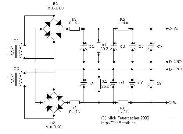
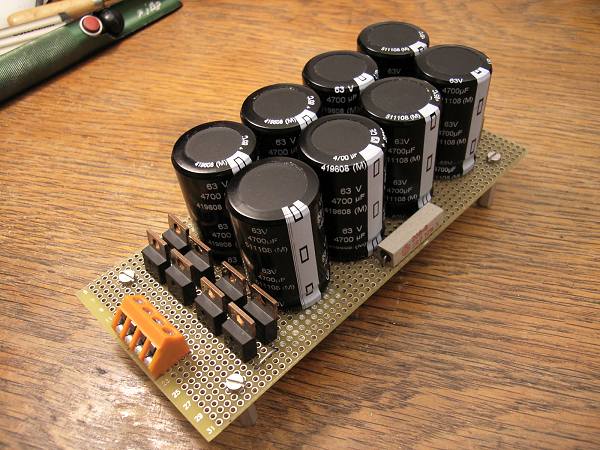
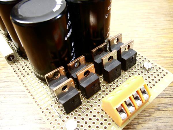
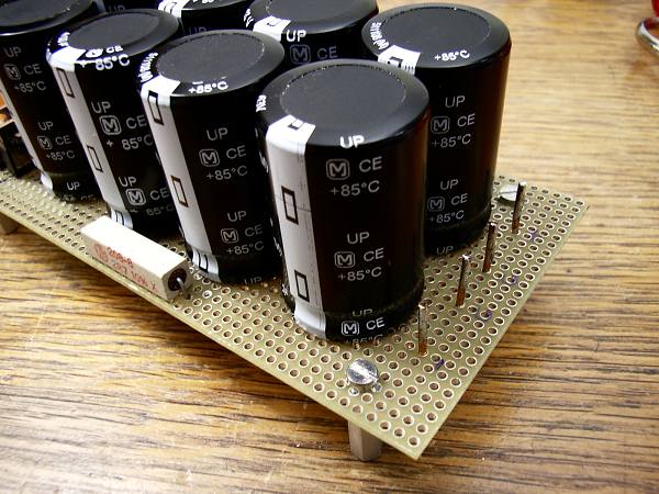
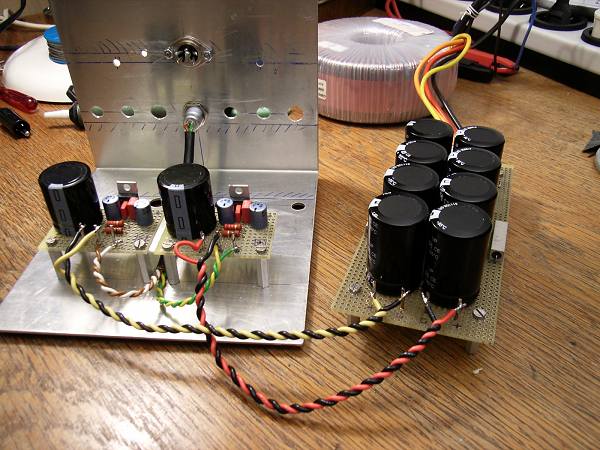
The schematic of the unregulated part. The transformer is has 2 x 30 V and is rated 300VA. The bridge is discrete and uses eigth MUR680 diodes. After that come two subsequent RCC filters and a bleeder. C1 to C8 are 4.700 µF electrolytic capacitors.

The RCC filters are used to effectively filter out the ripple voltage. With a total of 2R series resistance, the voltage drop at a current demand of 5A is 10 V. Therefore, with 42 V after rectification (using a 30 V transformator), the voltage, under extreme conditions, may drop to 32 
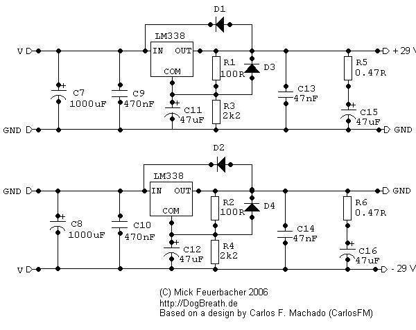
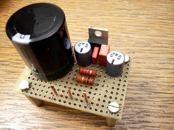
V. The following regulator is set to 29 V, so that the dropout voltage of 3 V of the LM338 is still available.
With this filter arrangement, the ripple voltage before regulation is only 3 mV (measured), i.e. less than 1/10.000 of the output voltage!

This part of the PSU is located in its own case, well separated from the amp.

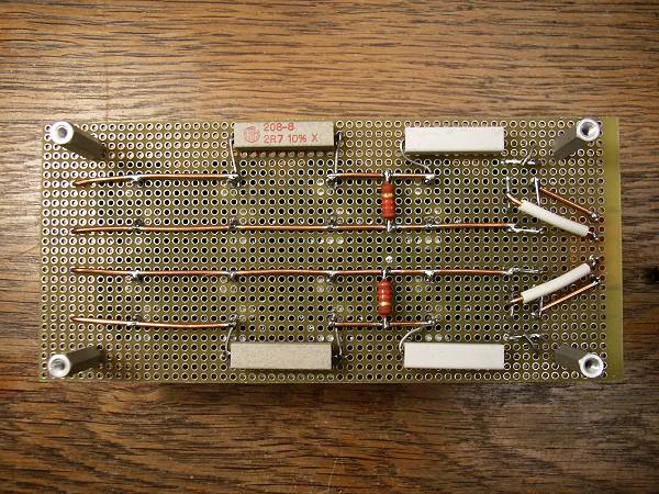
R3/R4 should be of 5 W, R5/R6 of 10 W type. These ratings should be ok during normal operation, which will involve current demands far below 5 A. Wirewounds can be used as stray inductance does no harm here. R1/R2 should be 2 W types. The resistor value is not critical but you should not use wirewounds here.


The schematic of the regulator part. C7/C8 are are reservoir capacitors used as the connection from the unregulated part is long (1 m or so). They can be omitted if the regulator is placed directly after the unregulated part.
It is of great importance that C9/C10 and C13/C14 are placed extremely close to the regulators! Solder the capacitors directly on the pins if possible.
The resistors setting the output voltage are chosen such that the latter is 29 V (see datasheet).
The regulator is equipped with a snubber on the output. The snubber values were calculated (and tested) by CarlosFM.


The finished unregulated part.


Bottom side of the unregulated part. For R5/R6 I used two 2R7 rated 5 W in parallel.


One of the regulators. The LM338 is placed on the edge of the board so that it can be connected to a heat sink. The capacitors on the input and output are extremely close to the pins of the LM.


The bottom side.


The bottom side during building. The resistors and the protection diodes are not installed yet. The middle wire is ground, input is on the right and output on the left.


A detail: I used a SMD resistor for the snubber. The 1 W types are rather large and can be conveniently handled.


The finished complete PSU during testing. Please note that, although not shown here, the LM338 needs cooling during operation.