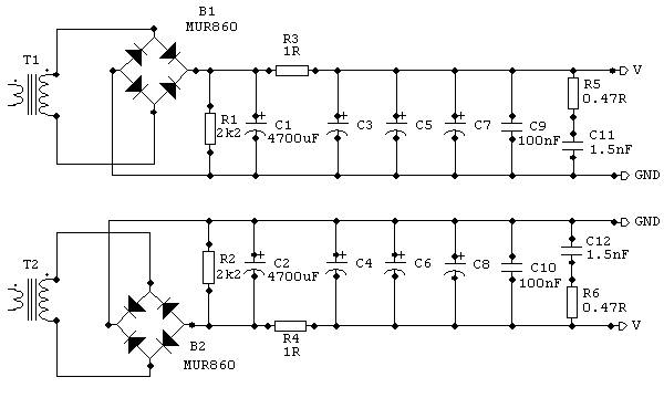
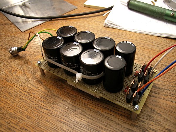
The schematic I used. The difference to CarlosFMs schematic is that I left the grounds of the positive and negative rail separated.The cable to the amp has four leads.
C3 to C8 are 10.000 µF capacitors.

A snubberized chipamp PSU
by Mick Feuerbacher, November 2005.
|
|
|
The schematic I used. The difference to CarlosFMs schematic is that I left the grounds of the positive and negative rail separated.The cable to the amp has four leads. C3 to C8 are 10.000 µF capacitors.
|
 |
|
|
 |
|
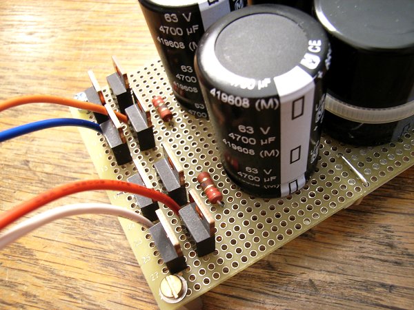
The rectifiers and the bleeders |
 |
|
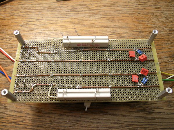
The bottom side. For R3 and R4 I used 11W wirewounds as a little stray inductance does not matter on this position. The 100 nF caps and the snubbers are directly soldered on the pins of the last 10.000 µF caps. The snubber resistors are two 1R 0.6W in parallel.
|
 |