A "copy" of the Gaincard amplifier

by Mick Feuerbacher, October 2005.


After an analysis of the 47 labs Gaincard amplifier, I wanted to build an amp which is very close to the original. The building process is described in the following.
In some points I deviate from the original Gaincard. As I have 4 ohm speakers, I used the LM3886 chip (the LM3875, used in the Gaincard, is not well suited for loads below 8 ohm) and a rail voltage of 27 V.


The schematic I used. The LM3886 has an additional mute function and a ground pin. I used the following parts:

Part Value Rating, type
Cin 4.7 uF 50 V polyester
Cs 2200 uF 63 V electrolytic
Cz 100 nF 100 V polyester
Rg 22k 1W carbon
Rf 22k 1/4 W carbon
Ri 680R 1/4 W carbon
Rm 10k 0.35 W metalfilm
Rz 2R7 2 W carbon


The PSU is as minimalistic as that of the Gaincard. One rectifier brigde (MUR860 diodes), no filter caps. With my 2 x 18 V toroid I got 26.7 V output. I did not connect the grounds in the PSU. Separate ground leads go to the amp (4 wires) and are connected there at the power ground star (see below).


The feedback R is soldered directly on the pins.


Rm is also soldered directly on the pins. I added a connection from pin 4 (V-) to pin 11 (nc), so that I could make the V- connection there and get a more symmetric layout.


Cin is soldered on pin 10.


Rz and the speaker + on pin 3. Also, make a connection between Pin 1 and Pin 5 (both V+). This connection is not shown on the pictures, as I installed it later in my amp.

I installed the amp on an aluminum bookend which I use as a sort of testing jig for different amp configurations.


Rg, Ri, Rz, and pin 7 are connected to the minus pole of the RCA connector. This is were the signal star ground is placed.


The first Cs cap and the voltage rails are connected.

In the front, the pot is seen. For testing I use a 50 k alps pot (which I took from the Audiodigit T-amp kit).


The right channel is finished.


The second channel is finished.


The amp and the PSU on my workbench. In the background my Dynaudio 100 test speakers are seen.


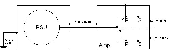
The grounding scheme. The mains earth is connected to the PSU case directly. 
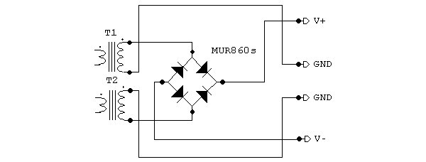
The two ground connections (+ and - grounds) are lead to the amp separately (see Fig. 2). The cable used for the PSU-amp connection is a shielded four-wire cable. The shield is connected to both the amp and the PSU cases.

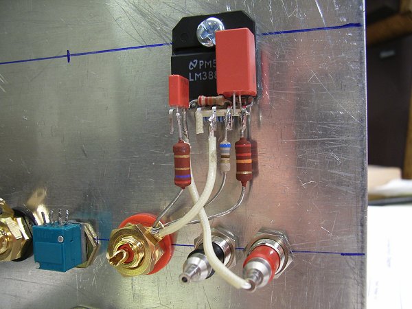
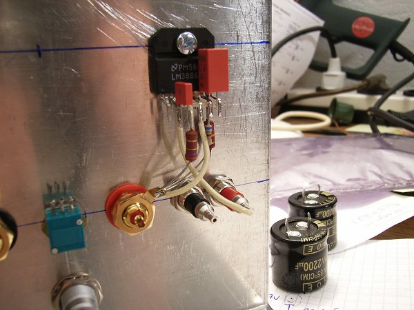
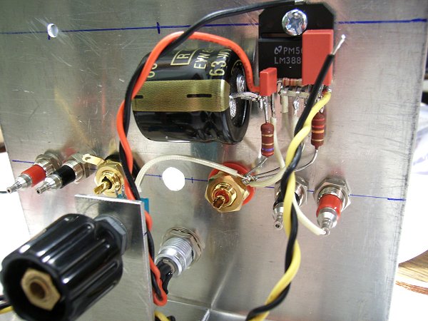
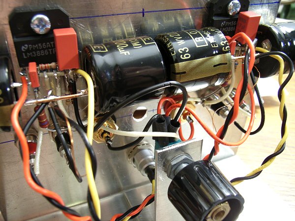
The ground connections coming from the PSU are split (left and right channel) in the amp and both are connected to the power star ground of 
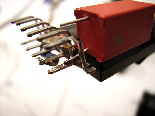
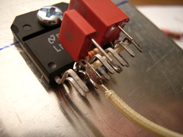
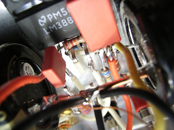
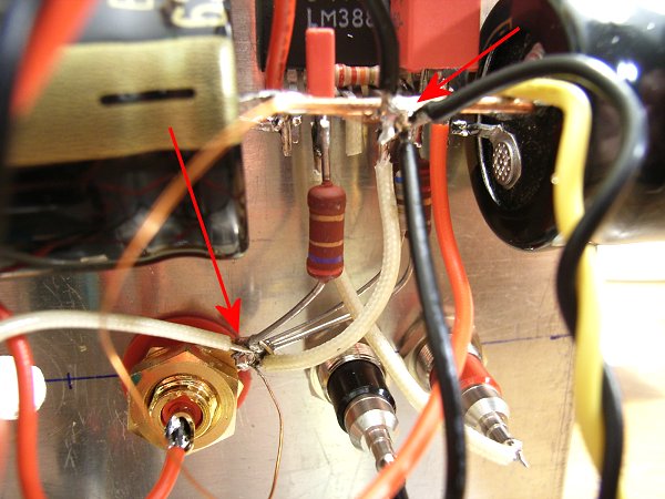
the respective channel. The power stars, as shown below, are connected to the signal stars by a thin wire. One power star is connected to the case.

At each power star the PSU grounds, the speaker return and the connection to the signal star are connected. All other grounds are connected to the signal star.

Note that the separation of signal and power star ground is another deviation from the original Gaincard layout.


The separate star grounds. The signal ground is on the minus pole of the RCA connector (lower arrow). The second legs of the Cs caps are connected using a thick copper wire. In the middle of this wire, the power star ground is placed (upper arrow). Here the two ground wires from the PSU (the separate + and - grounds) and the speaker return arrive.
The two star grounds are connected by a thin and relatively long copper wire in order to lift the signal ground by a small amount.
This grounding scheme is done independently for both channels. .


Test setup for measurement of the DC offset and the distortion tests shown below. The speaker is replaced by a 4R7 (11W) resistor over which the voltage is measured.


I tested the distortion (in a primitive manner) by feeding a 500mV 1kHz square wave into the amplifier.

This image shows the output at about half of the full volume setting (corresponding to a rather loud listening level). The amp produces a very nice and undistorted signal.


When the volume is turned up about 90 % of the maximum value, the waveform starts to change its shape. A small additional peak is seen at the beginning of each square and the voltage slightly drops over each cycle.