Another chipamp iteration: the copper amplifier

by Mick Feuerbacher, July 2007.


The current project is my latest iteration of a single-chip LM3886 design. The circuit is boiled down to the absolute necessary parts. It is even more simple than that of the three-resistor amp - I left out one more resistor, so now it is essentially a two-resistor descendant. The amp is build up double mono. The channels are completely separated and each has its own power supply.

This the first project where I started with the case. I wanted a very stable, small and optimized case. Furthermore I planned to place the chips on a large copper mount as this material has, according to several professional as well as diy builders, superior acoustic properties.


The schematic of the amp. The chip is a National Semiconductors LM3886.The following additional parts are used:


Part Value Rating, type
R1 10k log pot
Rf 22k 0.25W carbon
Rg 680R 0.35W metalfilm
Rm 10k 0.35 W metalfilm
Cs

2200 uF
|| 100 nF

50 V electrolytic;
100 V polypropylene


The build process


The central element: a big block of copper. The chip will be directly mounted on this block, which by itself will be connected to a copper support.


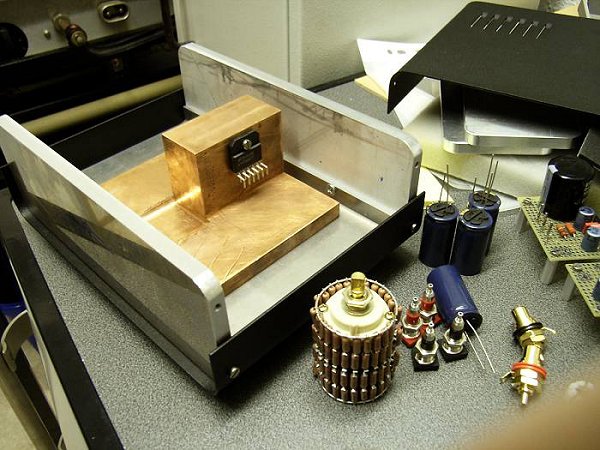
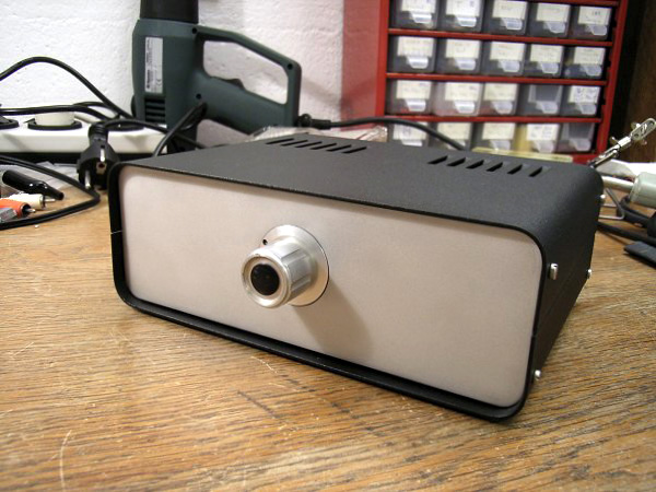
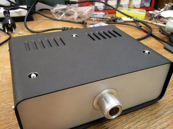
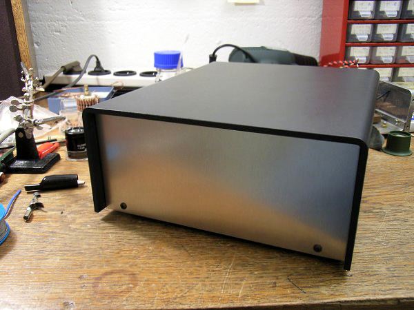
I decided to build the amp into a commercial case from Conrad. It turned out that the build quality of the case was very low. The front and back plates were made of awfully thin aluminum and the screw connections were worn right from the beginning.

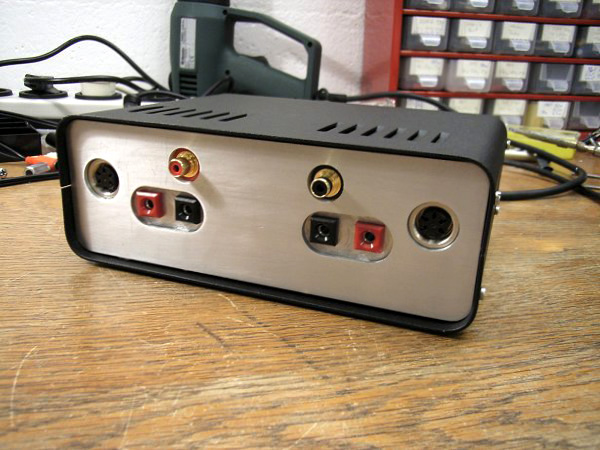
Therefore I only used the upper and lower steel covers and made the complete rest by myself, using massive aluminium. The front and back plates are 8 mm thick, the bottom plate is 4 mm.

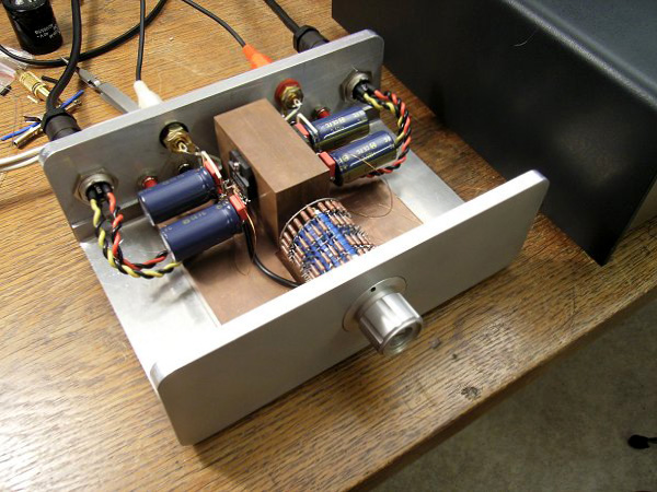
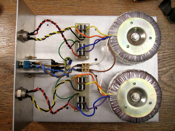
On the picture you also see some of the parts to be used. The Cs capacitors are well approved Panasonic FC types, the pot is a stepped attenuator as sold by http://diyfidelity.com.au/.


The LM3886 with the inner parts connected: you see the muting resistor, the pin1-pin5 connection, the redirection of V- to pin11 and, in the background, the feedback resistor.


The core part of the apm on the copper block. The wires to the connectors are already soldered to the chip.


The finished amp. The bottom copper support is decoupled from the aluminium parts by a layer of neoprene. The Cs capacitors are mounted directly on the pins of the chip in such a way that there are no current loops formed. The amp has separated signal and power grounds, which are connected by a long thin wire (approx. 0R3)

After completion the amp was subjected to the usual tests. The DC offset was only 6mV on each channel.


The front plate was grinded and sandblasted to give it a nice matte finish. After sandblasting, it was spray laquered to avoid corrosion.

The volume knob is recessed. For now I use a knob which I once found in a dumpster. It will later be replaced by a dedicated turned piece.


Back.


Bottom view: The inner unit stands on spikes and is not coupled to the outer steel cover


The power supply


With my other chip amps, I tried several versions of power supply. I tested high-capacity snubberized supply, switch-mode supply, discrete regulated and chip regulated supply. With this amp, I decided to go for the simplest solution, which was my first option and which I eventually preferred over all the others.

The PSU consists of a rectifier bridge - one per rail - only. There is no capacitance, only the 2200uF directly at the chip as seen above.


The finished PSU. It is built up completely double mono. The toroids are 2 x 18V, 120 VA types.


Back


Front


The copper amp in my system


The copper amp is now continuously running since a couple of days in my system. I am very pleased with the sound and, compared with my previous iterations, it has increased detail in the mids and highs, and a temendous dynamics.

The source is a heavily modified Sony Playstation 1 with an external linear power supply, the speakers are Audio Physic Tempo IIIi.


A view from the back.